ALTTP's Tragic Trajectory Calculation
A lot of people like to call Agahnim 2 a "geometry test", but I don't. It's not because I'm being all pedantic and thinking Oh, well, actually, it's trigonometry, not geometry.
No, no—my qualm is that the quote-unquote "geometry" of Agahnim 2 is really bad.
I'm not going to campaign against this joke, but I do want to make it known just how bad this math is. If you look at all 360 degrees of a circle, Agahnim gets the correct answer 4 times, only twice as accurate as the proverbial broken clock.
The specific calculation I'm talking about is the one that helps entities move from one location to another in a straight line. It isn't just used by Agahnim 2, but by pretty much everything that needs to move towards or away from an arbitrary point. This calculation is called from 114 unique places, including pretty much any action that causes Link or a sprite to recoilCertain sprites—such as fire bats—don't use this calculation for knockback. Instead, they just invert your speed on each axis and call it day..
Projecting
This routine, which we'll call
This disassembly removes all the overhead of transforming coordinates into distances, sorting those distances, etc., and just focuses on the meat of the algorithm. One of the speeds (that of the axis with the larger displacement) will be given the input speed while the other axis will be given the accumulated speed calculated with this loop.
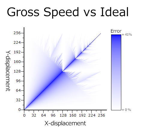
There are several problems with this algorithm, the most glaring being how one axis is fixed to the input speed. Rather than rotating a line, this is more like pulling and stretching it. The fixed component results in a floor for the gross speed that is irrespective of angle. This means the calculation is only correct when one of the distances is 0, with the error increasing proportionally to the smaller displacement. In the worst case scenario—when the displacement on each axis is equal—the error is as bad as 41%When the displacements are equal, the speeds will be too. That gives a calculated:ideal ratio of √2:1, or 141.4%..
This algorithm is also subject to overflow errors. Everything is limited to 8-bit operations, and the algorithm remains well-behaved for all values below 128, but there's a danger zone above that. As an example, imagine our points are separated by 250 pixels on the X-axis and 230 pixels on the Y-axis. Our first iteration will end with a total of 230—that's correct—but when we perform the next iteration, our total is 204. Even though the value overflowed and should have accumulated some speed, it didn't.
Art exhibit
To get a better idea of how bad this algorithm gets in practice, we should look at actual resultsThese graphs all used a ported version of the vanilla code with a fixed speed of 256. Using such a high value is moreso displaying the limiting behavior of the algorithm. Any sufficiently high speed (at least 16 or so) will show the same basic pattern, but probably won't produce an identical graph to what's shown here. I'm not analyzing 250-whatever graphs.. Below is a graph that takes every possible pair of displacements and plots the error in gross magnitude at that point. The bluer it is, the wronger.

There's an immediately obvious line bisecting the graph. This is the worst-case-scenario line, where the displacement on each axis is equal. The closer a point is to that line, the more speed it has over the input speed, up to that maximum 41%. Ignore the apparent exceptions for just a second.
If you stare, you'll notice another line: an anti-diagonal going from the top of the Y-axis to the right end of the X-axis. The area above this line is where overflow errors become increasingly problematic. There's some pretty chaotic behavior in the error, with crystal-esque visuals on either side of the worst-case line. In the upper-right quadrant, where both X and Y are greater-than-or-equal-to 128, the graph reveals its fractal nature.
However, the graph is a bit misleading. In many of the extreme cases, the error looks really good, but that's just because the secondary axis had no opportunity to build up due to overflow errors. For example, a displacement of (255, 253) shows an error at or near 0. That sounds good, but that speed is entirely on the X-axis. What should be an angle of 44.7° is an angle of 90°.
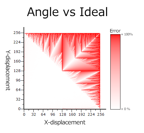
To gain a better understanding, we need to look at a plot of the error in the resulting angle.

In this graph, we find that the area below the overflow line is very well-behaved. The extremely shallow and extremely steep angles suffer from rounding errors, but it's never worse than 50%—only a couple of degrees at these angles. Above the overflow line, it's awful.
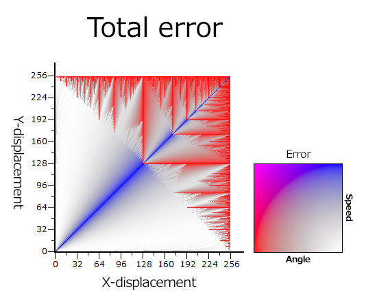
The worst-case-scenario line for speed is actually the best-case line for angle. It's not too hard to understand why. Equal speeds for equal displacements. In fact, the angle and speed errors are almost perfectly complementary. When the angle is wrong, the speed is fine, and vice versa. If we do a combined graph, we can see this delicate, accidental balance. If there were significant overlap, there would be areas of vibrant, opaque purple.

In addition to plotting individual errors as color coordinates, the total error is encoded in the alpha channel.
The Big O
In addition to being completely wrong, this calculation is also incredibly slow. The complexityI'm using "complexity" to mean value of the input, not size. And, actually, big theta would probably be more appropriate, but I think more people are familiar with big O. of this routine is O(n) for a given speed n—it runs in linear time. Which, okay, that's not the worst. But it can and should be O(1).
Another way to think of this routine is as the function speed×(smaller/bigger), where smaller and bigger are the distances between the current and target coordinates on the X- and Y-axes, respectively by size. This might leave you scratching your head for a moment, but that can also be interpreted as speed×tan(θ), which means we're using a trigonometric function. That's good. Those things are for angles!
On a less powerful system, such as the NES, this would actually be a pretty cute algorithm. It cleverly combines multiplication and division into a single loop, where normally each would need its own. But as soon as you have the ability to multiply and divide without a manual loop, this method is terrible.
While the SNES doesn't have any instructions for these operations, it does have dedicated hardware registers. CPU multiplication works with an 8-bit multiplicand and an 8-bit multiplier; and division works with a 16-bit dividend and 8-bit divisor. Below is an example implementation of
The only downside to these registers is that they take some time to perform a calculation—8 cycles for multiplication and 16 for division. In the code above, the wait time for multiplication isn't even a bottleneck, as we have a little bit of prep work before we read the result. The division does require waiting though.
But even with the wait time, this is still loads faster than the original implementation. The vanilla code requires 23 cycles per loop iteration, or 29 if the
And remember: this is a one-and-done; this implementation always takes the same amount of time. What I have above isn't even the most efficient it can get. By rewriting (and optimizing) the preparatory calculations, this code can be improved even furtherSpecifically, some clean up work can be done during the division wait cycles. Otherwise, there's nothing else to optimize with the actual calculation..
As an added bonus, this implementation is also not subject to the rounding errors that threw off the angles for larger distances.
Still bad
Let's say, for whatever reason, we can't use the CPU arithmetic registers, or we just don't have any. The vanilla code is still inefficient. Compare the snippet below to the original disassembly:
This rewrite makes several changes to vastly improve the speed from 23/29 to 14/20 cycles per loop, with the numbers in each pair being the number of cycles for whether the
- The A register doesn't need to read and write its value into memory each time. Nothing is clobbering it at any point.
- Incrementing memory directly is slower than incrementing Y. The original code uses this register to hold the state of something else, but that's easily worked around, and doing so is worth it for the speed gain within the loop.
- The state of the carry flag is determinate half of the time. If the branch is taken, it was taken because the carry was clear, and it will stay that way on the next iteration. It's only necessary to manually clear the carry before the loop and after subtraction. For some inputs, this is a significant savings. In the worst case scenario, the instruction's contribution to CPU time is equal to that of the original code.
At this point, I'm just dunking on the devs.
So what?
Okay, but is this routine really that bad? Yes and no.
In a lot of cases, this is probably fine. Rounding means that even a geometrically-correct calculation will have non-negligible error. Such a calculation would also come at some cost. The vanilla game already has a table for sine and cosine, but those would require knowing an angle. Getting the arctangent of a number requires a lot of calculation time or an obscenely large lookup table.
I think the most noticeable result of this bad calculation is the red spear guard on the library screen post Agahnim, lovingly known as Usain Bolt. I've heard people say it feels like he runs faster when he comes at you diagonally. Well that's because he does. And now you know why.
Summary
The way ALTTP tries to rotate a vector towards a point is mathematically wrong. The more it has to rotate, the more it increases the magnitude of the vector—up to 41% longer. It's also slow, and large distances behave erratically. But unless you're specifically looking for it, you likely won't notice the speed boost except in the most extreme cases. The contribution to lag can get pretty serious, though.
Continue calling Agahnim 2 "geometry class". Just know that this guy failed geometry himself, so he's not going to be the best teacher.